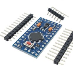
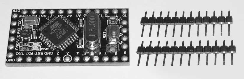
Solder the 12-pin headers on the Arduino.
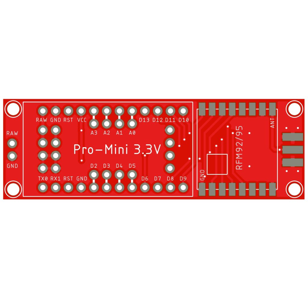
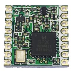
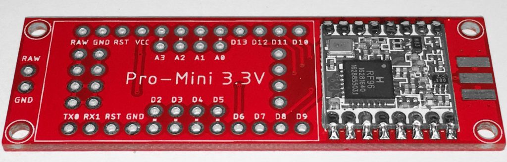
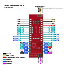
Solder the HopeRF RFM92/95 module on the PCB. Check the reference pads with the PCB and the RFM module. The white square on the PCB is the position of the IC on the RFM, and the ANT position is marked.
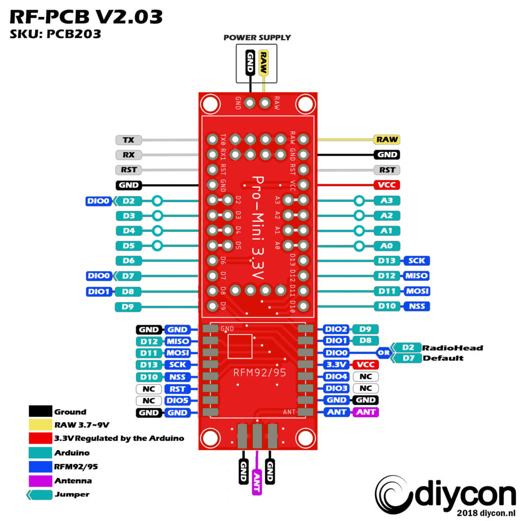
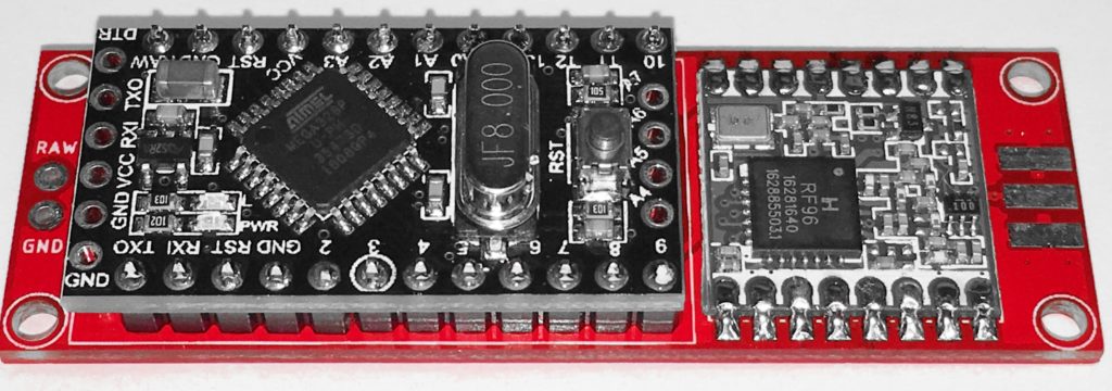
Solder the Arduino on the LoRa Interface PCB. Check these reference pins on the PCB with the Arduino: D9, D10, RAW, GND.
With the solder jumper on the backside from the PCB you can choose between 2 digital pins from the Arduino to the RFM DIO0 pin. D7 is the defualt pin we use if you want to use the RadioHead script you must select D2 because this script uses interrupts.
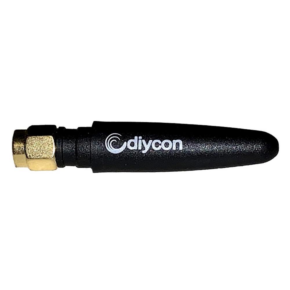
Solder an antenna on the board. There a several antennas available in the market.
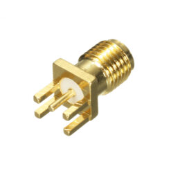
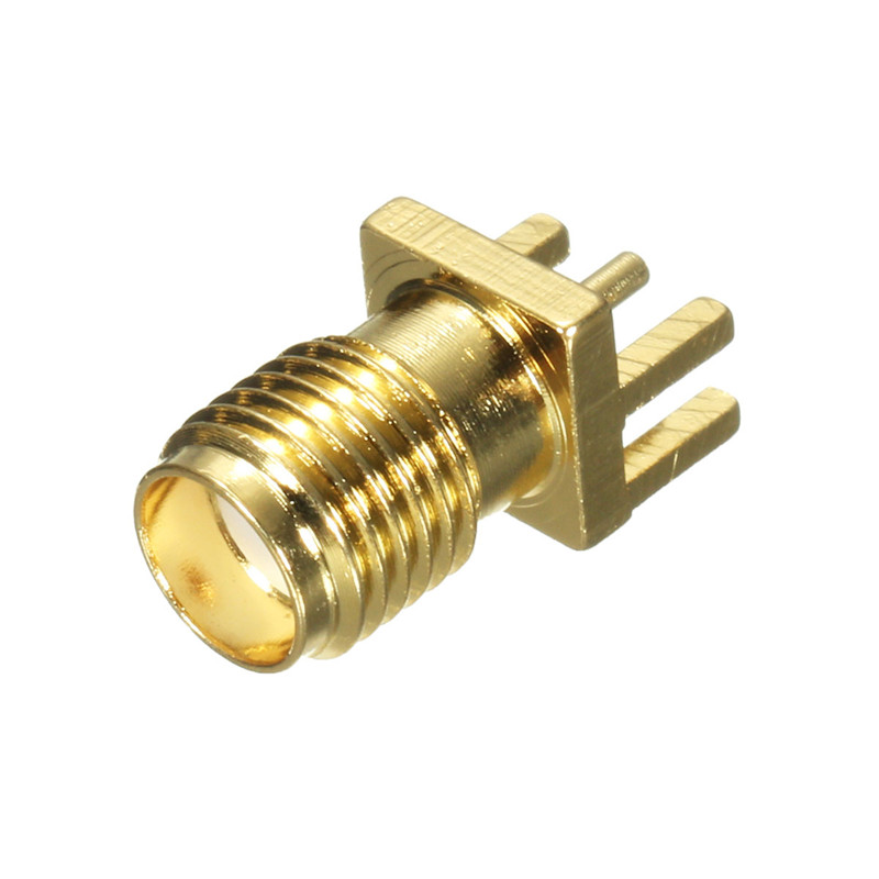
On this board you could solder a SMA connector, and connect the antenna of your choice. Or you can use a coil antenna or 8,2cm copper wire as antenna.
The Arduino Sketch
- Download the Arduino-lmic-master Library
- (original library can be found here, you must edit the pinmapping)
- You can find a copy of this library on our Github page with the correct pinmapping for this PCB. Copy this library folder to your Arduino library folder.
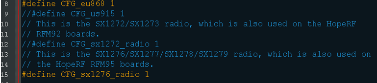
- Check the radio configuration in /library-folder/arduino-lmic-master/src/limc/config.h.(line 8 -> 15)
- Select the radio frequency you want to use: 868MHz or 915MHz.
Select the radio type you are using RFM92 = sx1272 or RFM95 = sx1276.
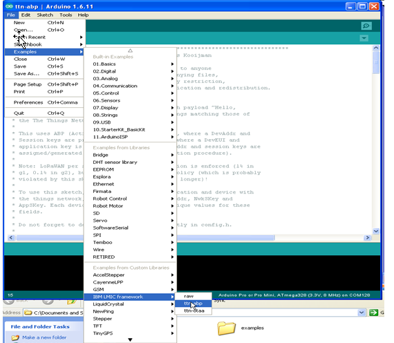
After importing the library into the Arduino IDE
Select -> Open: FILE -> Examples -> IBM LMIC framework -> ttn-abp or ttn-oota
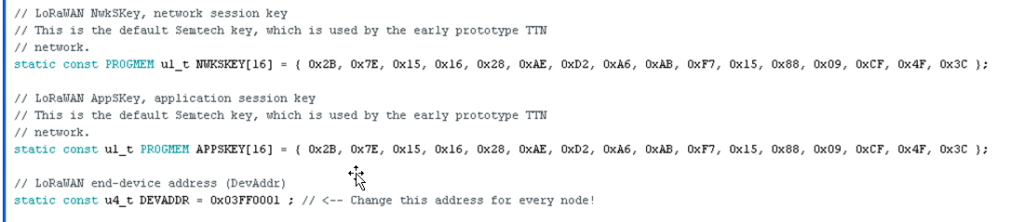
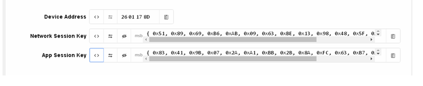
Replace the network session key, application session key and device address at the top of the sketch.
With the keys en address of your account (TheThingsNetwork dashboard)
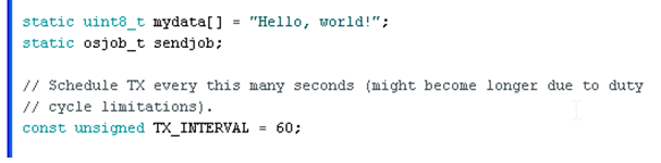
In the next section you will find the payload messages and the interval between the messagestime is in seconds.
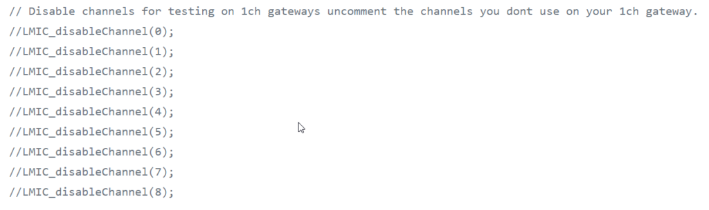
If you are using a single channel gateway you can disable channels on line 204
Uncomment the channels you dont use.
Upload the Sketch
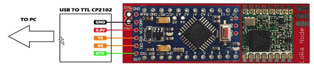
Connect your LoRa Interface PCB to the USB to TTL converter
WARNING ONLY USE 3.3V ON THE VCC OR YOU WILL DAMAGE THE RFM MODULE!!
IF YOU DON’T HAVE A 3.3V POWER SUPPLY PLEASE USE THE RAW PIN ON THE PCB.
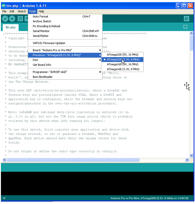
Set Board -> Arduino Pro or Pro Mini
Set Processor ->ATmega328 (3.3V 8 MHz)
Set Port -> COM port of the TTL converter.tpat.
Upload the sketch
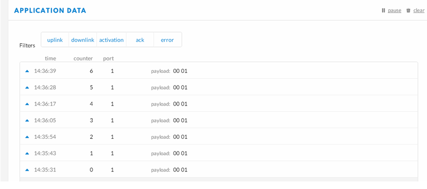
After successful uploading the sketch, you can check if the node is working in the serial monitor, or in the dashboard of your TheThingsNetwork account.
For range testing you can download the app TTNmapper on your phone use your the TTN device adress and access key for setting up the app.
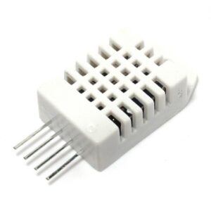
To see how to connect a sensor on your board please see the page
Connecting a Sensor on your node