LoRa Node PCB 203 for Interface Pro Mini RFM92/RFM95
€2,49
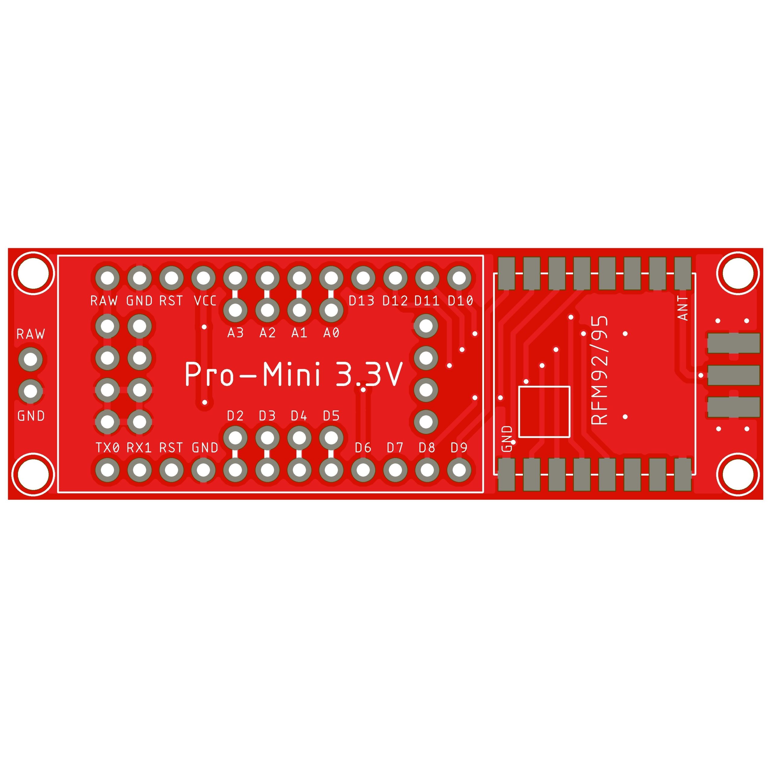
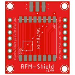
Create a simple LoRa IOT Node with this interface PCB. This board is perfect for learning and experimenting with LoRa. The PCB makes all the necessary connections for the LoRa module. Just add a Arduino pro-mini 3.3V and a HopeRF RFM95/92 LoRa module to the PCB and you are ready to go. At the bottom of the PCB you can connect different types of sensors and modules.
This board is tested with the following libraries:
New Tutorial TTN V3
https://github.com/mcci-catena/arduino-lmic
https://github.com/sandeepmistry/arduino-LoRa
https://github.com/hallard/RadioHead
In stock
Power supply:
Use the RAW pin of the PCB for power supply. The Arduino Pro-mini 3.3v regulates the voltage to 3.3v for the HopeRF RFM92/95 module. At the bottom of the PCB are extra connections for powering sensors or other modules.
Only use an Arduino Pro-mini 3.3v version on this PCB!!
The HopeRF RFM92/95 only works on 3.3 volt higher voltage will damage your LoRa module!!
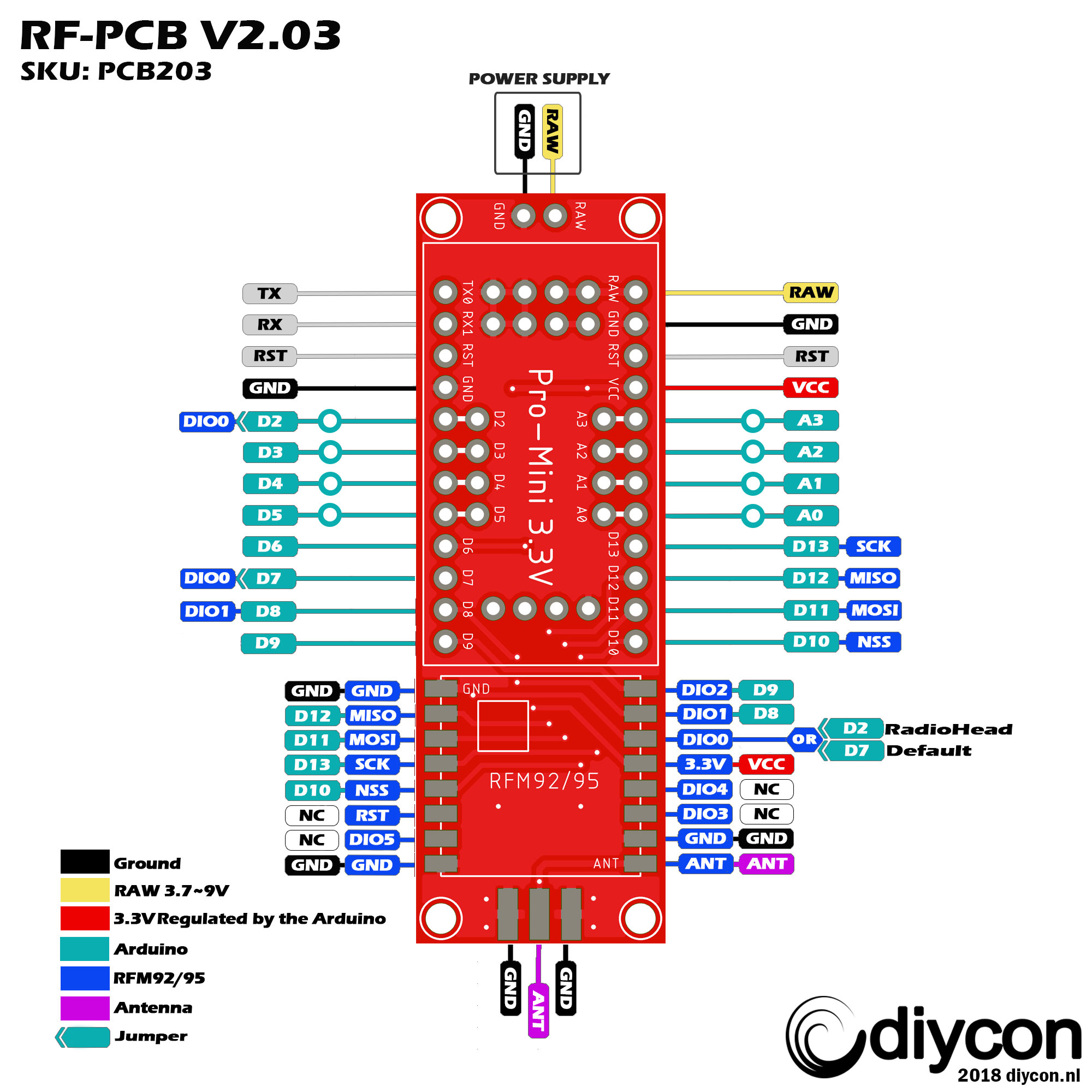
Connections:
The PCB makes all the necessary connections from the Arduino to the HopeRF RFM92/95 module.
MISO, MOSI and SCK are connected to the standard arduino pins.
The only thing you need to change in your sketch are the DIO and the NSS pins
Short manual how to get this board working TTN V2— New Tutorial TTN V3
This board is tested with the following libraries:
https://github.com/mcci-catena/arduino-lmic
https://github.com/sandeepmistry/arduino-LoRa
https://github.com/hallard/RadioHead
Change the pin-mapping in your sketch to mach with the pin-out table below. (DIO0, DIO1, DIO2 and NSS pin)
If you use the LoRa-lmic library you must provide your – network session key, application session key and device address.
| RFM95 | Pro-mini 3.3v |
| DIO0 | 7 |
| DIO1 | 8 |
| DIO2 | 9 |
| NSS | 10 |
| MOSI | 11 |
| MISO | 12 |
| SCK | 13 |

| Weight | 10 g |
|---|---|
| Dimensions | 6 × 2 × 2 cm |
1 review for LoRa Node PCB 203 for Interface Pro Mini RFM92/RFM95
Only logged in customers who have purchased this product may leave a review.



Siegfried MARECHAL (verified owner) –
Very nice board, i love it!