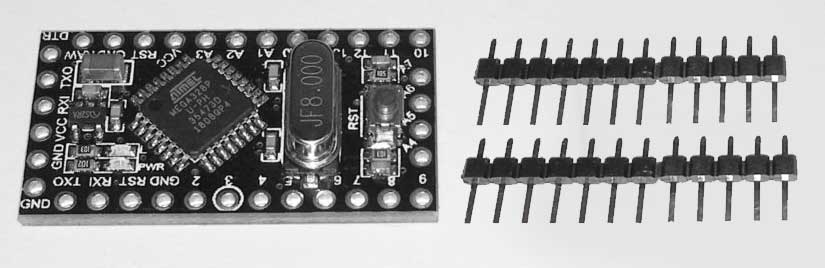
Solder the 12-pin headers on the Arduino.
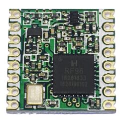
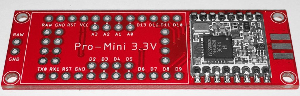
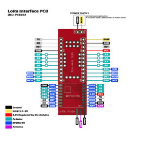
Solder the HopeRF RFM92/95 module on the PCB. Check the reference pads with the PCB and the RFM module. The white square on the PCB is the position of the IC on the RFM, and the ANT position is marked.
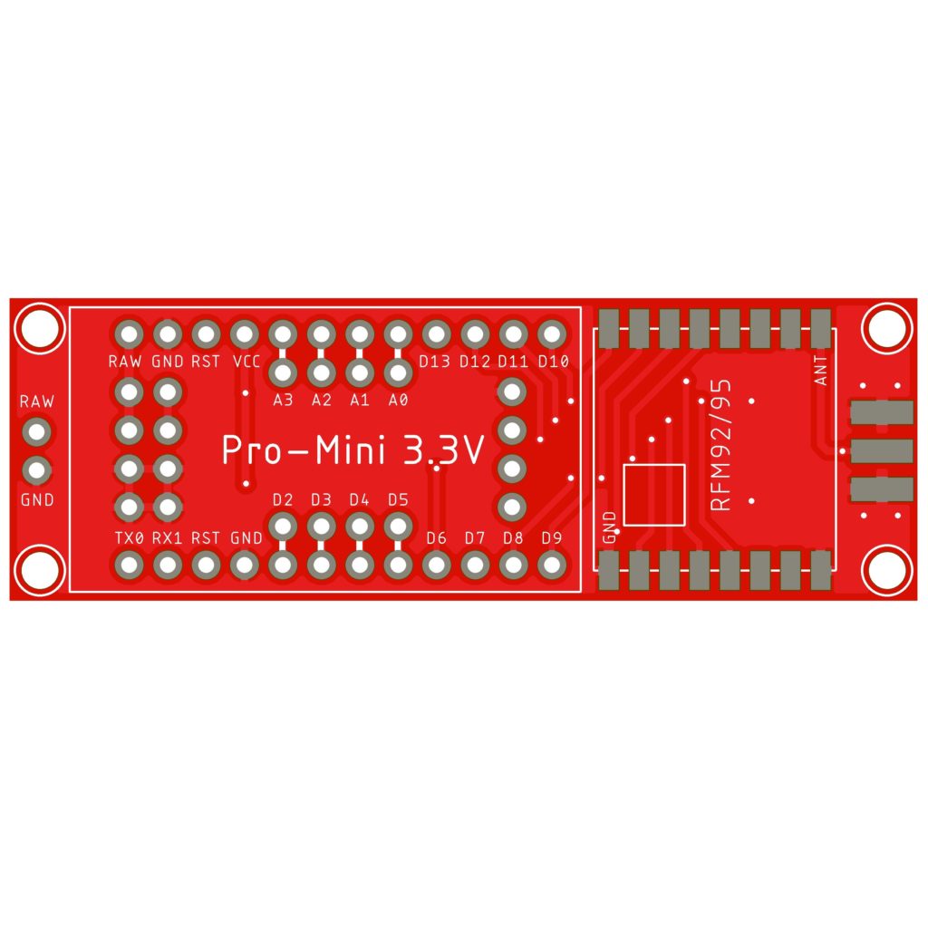
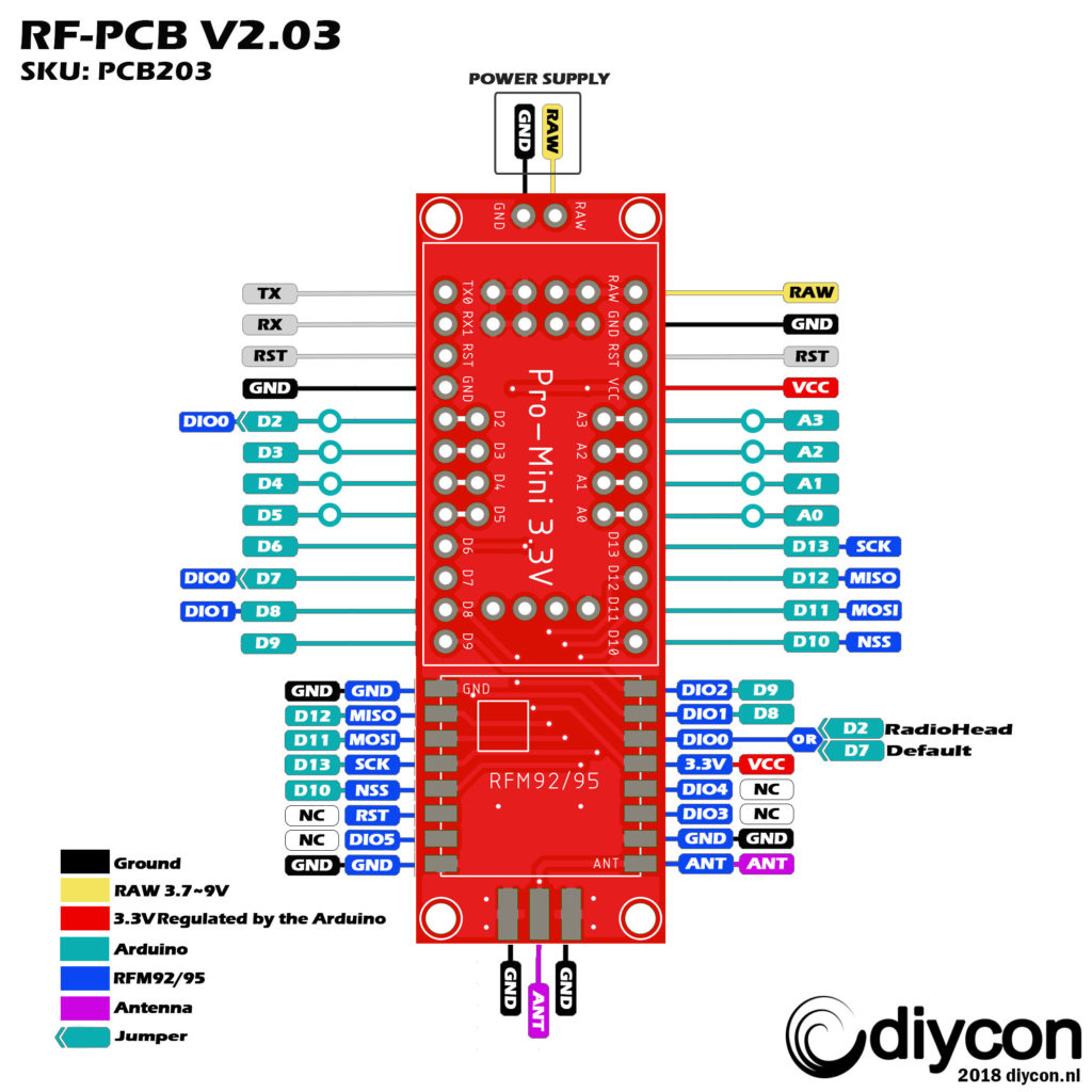
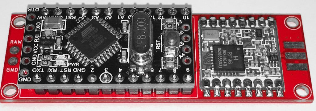
Solder the Arduino on the LoRa Interface PCB. Check these reference pins on the PCB with the Arduino: D9, D10, RAW, GND.
With the solder jumper on the backside from the PCB you can choose between 2 digital pins from the Arduino to the RFM DIO0 pin. D7 is the defualt pin we use if you want to use the RadioHead script you must select D2 because this script uses interrupts.
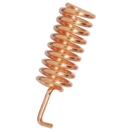
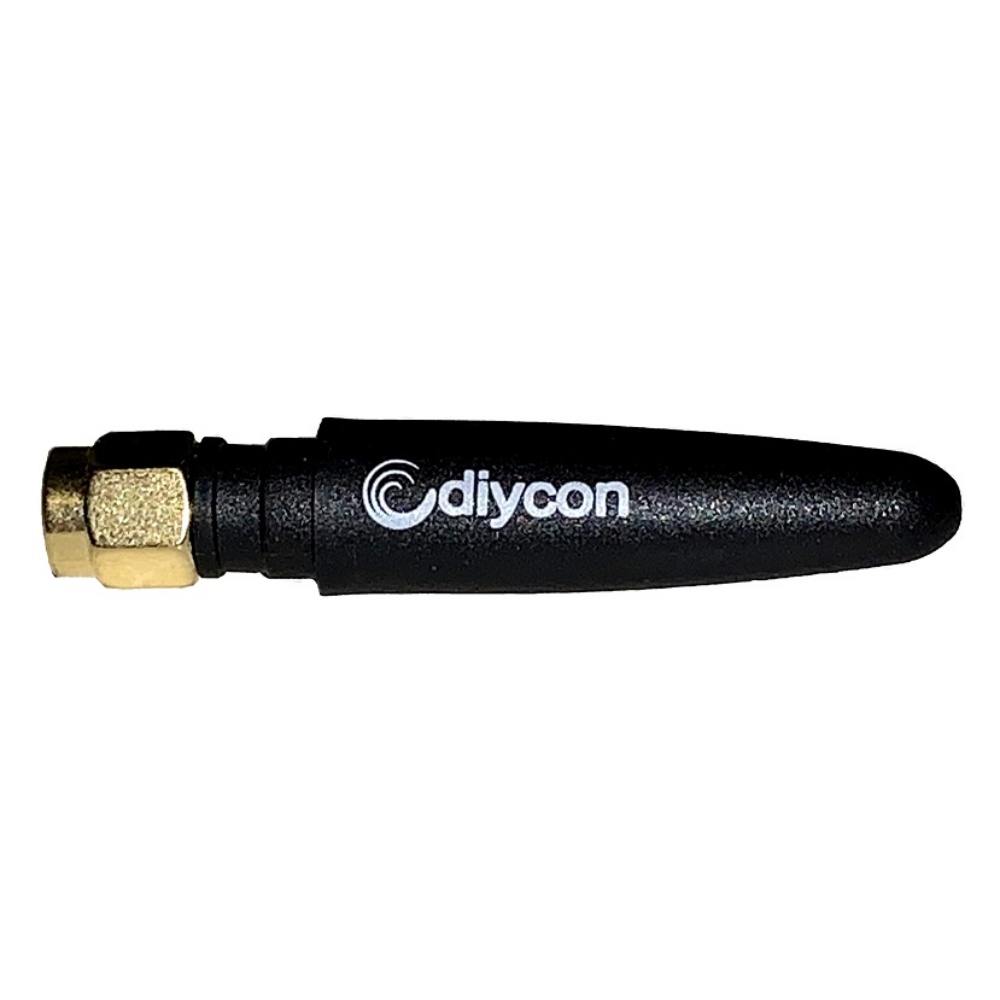
Solder an antenna on the board. There a several antennas available in the market.
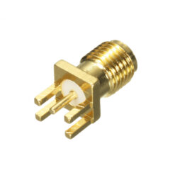
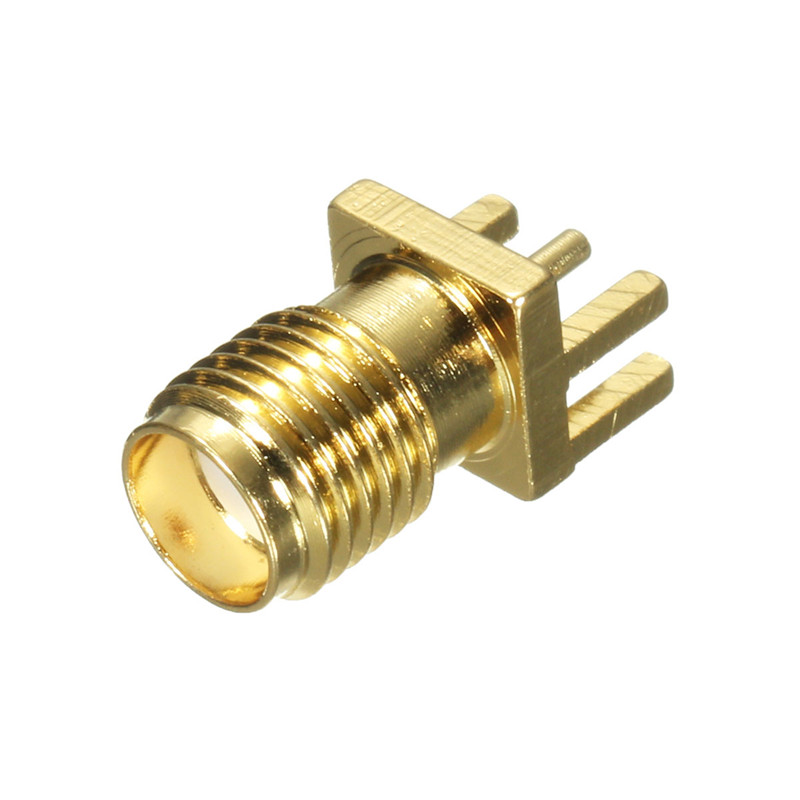
On this board you could solder a SMA connector, and connect the antenna of your choice. Or you can use a coil antenna or 8,2cm copper wire as antenna.
The Arduino Sketch
- Download the MCCI LoRaWAN LMIC Library
- Copy the library to your Arduino library.
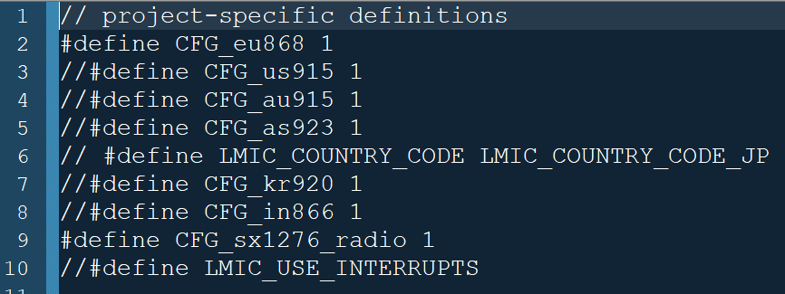
- Check and select the radio frequency you want to use in /library-folder/arduino-lmic-master/project_config/lmic_project_config.h see below.
After importing the library into the Arduino IDE
Select => Open: FILE => Examples => MCCI LoRaWAN LMIC library
There are a number of examples available in this tutorial we are going to use the TTN_ABP and TTN_OTA example sketch.
For more information about the library and other settings please visti the Github page from MCCI-CATENA.
Please visit TheThingsNetwork ABP vs OTA page to learn more about ABP and OTA.
Open the example TTN_OTAA sketch.
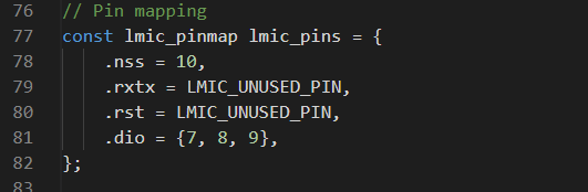
First edit the pinmapping section line 77. edit the pin numbers for
- NSS => pin 10
- RST => LMIC_UNUSED_PIN,
- DIO 0,1,2 => pins 7, 8 ,9.
Creating an OTAA device in the TheThingsNetwork dashboard.
Go to your TTN dashboard and create a new application or use an existing application.
In the overview of your application click on End Devices (left menu).
Here you see an overview of your devices on the upper right side click on Add Device and select Manually like below.
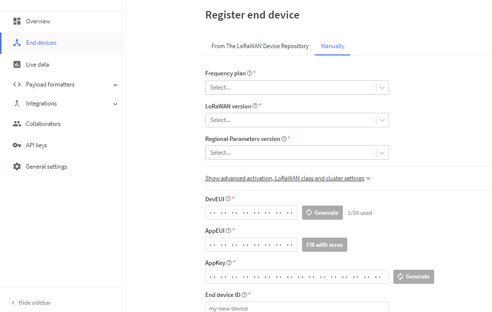
First select the frequency you want to use in our case EU 868MHz we choose the recommend one,
Next select LoRaWAN version according the firmware its compatible with MAC v1.0.3.
Next create the keys DevUI, AppEUI and Appkey if you dont have own keys click on generate the AppEUI will be filled with zeros you can use these in your script.
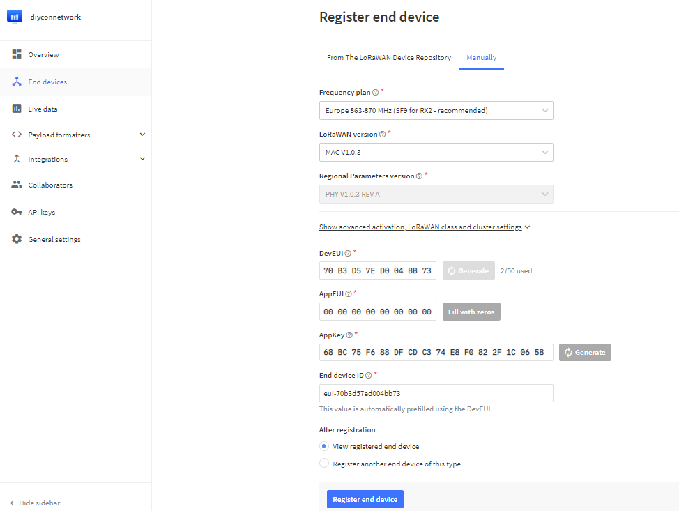
Click on Register End Device
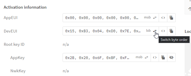
Next copy the following keys to your script
- APPEUI default { 0x00, 0x00, 0x00, 0x00, 0x00, 0x00, 0x00, 0x00 }
- DEVEUI in LSB format < see screenshot below
- APPKEY in MSB format< see screenshot below
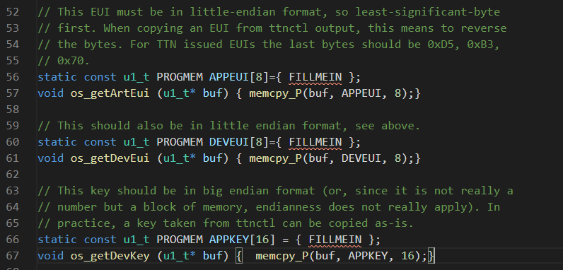
Replace the FILLMEIN with your keys line 56 ~ 66 of your sketch see below.
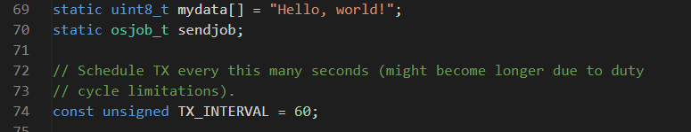
At line 69 ~74 you can ind the payload message and the interval between the messages the time is in seconds the payload is (Hello, world!) this is only for testing you can replace the this later with your sensor data explained in a other tutorial.
Upload the Sketch
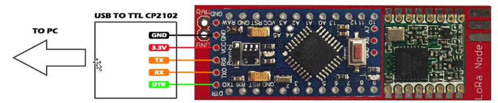
Connect your LoRa Interface PCB to the USB to TTL converter
WARNING ONLY USE 3.3V ON THE VCC OR YOU WILL DAMAGE THE RFM MODULE!!
IF YOU DON’T HAVE A 3.3V POWER SUPPLY PLEASE USE THE RAW PIN ON THE PCB.
Set Board -> Arduino Pro or Pro Mini
Set Processor ->ATmega328 (3.3V 8 MHz)
Set Port -> COM port of the TTL converter.
Upload the sketch if you have some connection errors during uploading push and hold the reset button of the Arduino then click Upload in the IDE and release the button when Compilation complete.appears.
After successful uploading the sketch, you can check if the node is working in the serial monitor,and in the Live Data screen at your TTN dashboard.
OTAA devices will send first a join request to the network this can take some time.
Serial Monitor example.
Live data monitor TheThingsNetwork.